
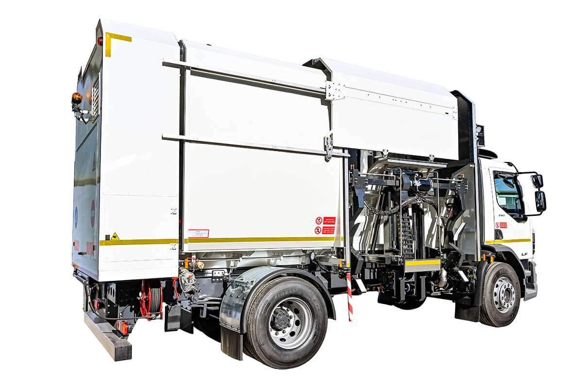
SIDE LOADER BIN WASHER WITH SEQUENTIAL INTERNAL/EXTERNAL WASHING - COLD WATER
DATA SHEET
| 1 | POSSIBLE vehicles | Brand | Model | Wheelbase | ||
| DAF | 75CF250 | 3900 | ||||
| IVECO | EUROCARGO 180 | 4185 | ||||
| IVECO | S-WAY | 4200 | ||||
| IVECO | S-WAY METANO | 4500 | ||||
| MAN | TGM 18.240 | 4425 | ||||
| MERCEDES | ATEGO 1726 | 4760 | ||||
| PTO | - Linked to the gearbox | |||||
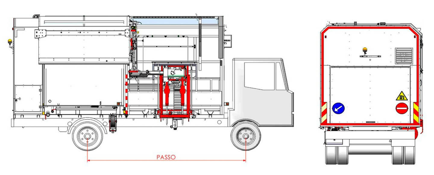
| Set up vehicle: | - The vehicle must have the right side (direction of travel) EMPTY between the front and the rear axle. | |||||
| - The cabin of the vehicle must have a rear window and individual passenger seat. | ||||||
| - Exhaust facing downward. | ||||||
| 2 | Water tank divided in 3 parts | Construction material | Tank | AISI 304 STAINLESS STEEL | ||
| Geometric capability CLEAN WATER | LITRES 6.000 | |||||
| Geometric capability DARK WATER | LITRES 5.800 | |||||
| 3 | Washing chamber | Construction material | Structure | ALUMINIUM | ||
| Covering | ALUMINIUM | |||||
| 4 | Rear box | Construction material | Structure | ALUMINIUM | ||
| Covering | ALUMINIUM | |||||
| 5 | Turning containers device | Construction material | Rotary Actuator | CARBON STEEL | ||
| Grasp arms with exit from the bottom | CARBON STEEL | |||||
| 6 | Washing system | AISI 304 STAINLESS STEEL TELESCOPING WASHING ROBOT | ||||
| Sequential modality | INTERNAL - With n° 2 AUTO-ROTATING HEADS 30 lts - 145 bar | |||||
| EXTERNAL - With 8 MOVABLE NOOZLES put on the SLIDING door | ||||||
| COVER - With AISI 304 steel FIXED BARS with 6 FIXED STREAM NOZZLES | ||||||
| Washing time | Set up on monitor | |||||
| Water use | 20 litres per wash at 20 seconds | |||||
| Stop and Go | 67 seconds with wash at 20 seconds | |||||
| 7 | High pressure pump | Construction material | Stainless steel pistons with plasma ceramic finishing touch | |||
| Steel control pistons with superficial treatment | ||||||
| Flow rate | Litres /minute | 60 | ||||
| Max pressure | Bar | 145 | ||||
| 8 | Dirty water pump | Self-priming centrifuge with open impellers | ||||
| Flow rate | Litres /minute | 100 | ||||
| 9 | Clean water loading system | Water supply network pressure with UNI 45 hydrant | ||||
| 10 | Dirty water drain system | With 3” valve | ||||
| 11 | Oil pump hydraulic services | Flow rate | Litres /minute | *** 28 | ||
| *** flow rate might vary depending on the model of the chassis | ||||||
| 12 | Oil pump pressure water wash | Flow rate | Litres /minute | *** 63 | ||
| *** flow rate might vary depending on the model of the chassis | ||||||
| 13 | PLC Monitor | N° 1 - 7’’ COLOUR TOUCH SCREEN | ||||
| 14 | Cameras | N° 1 – centring container | ||||
| N° 1 – lateral vision working right area | ||||||
| N° 1 – global vision working left area | ||||||
| 15 | Vision cameras Monitor | N° 1 – 7’’ COLOUR | ||||
| 16 | Security devices | N° 2 orange rotating lights | ||||
| N° 1 lateral safety bar | ||||||
| N° 1 security bar | ||||||
| N° 3 safety switch in rear box door | ||||||
| N° 1 safety switch in washing chamber door | ||||||
| N° 2 stop button (cab and control area) | ||||||
| Automatic slowing down in case of wrong movements | ||||||
| Alarms and visual signs in case of problems | ||||||
| AISI 304 stainless steel washing chamber with ALUMINIUM covering | ||||||
| 17 | Optional on request | Internal/external washing bins 1100 litres flat lid | ||||
| Internal/external washing underground bins - maximum height 1700 mm | ||||||
| Hot water with anti-limescale system | ||||||
| Hose reel kit H.P. lance and 20 mt. | ||||||
| Disinfection kit | ||||||
| Detergent kit | ||||||
| Rear camera | ||||||
| Inner washing chamber camera | ||||||
| Automatic Lubrication |
The above mentioned data is not binding and moreover is referring to the maximum potentiality of the single details.
AEP Allestimenti Speciali srl , on the pursuit of S&D politic of own products, reserves to make changes without notifications in respect of the reported data in this file.
AEP SIDE LOADER BIN WASHER TECHNICAL DESCRIPTION
1. TANK
To maintain the correct weight distribution on the vehicle’s axles, the tank is composed of interconnected external tanks for clean water storage and a central one for the dirty water coming from the washing chamber. This configuration ensures compliance with axle load limits imposed by regulations, as well as safe vehicle handling throughout the entire bin-washing operation cycle.
The material used for its construction is AISI 304 stainless steel, whose key characteristic is its excellent resistance to corrosion in various environments, including atmospheric conditions and many moderately aggressive chemical solutions. In addition to its corrosion resistance, AISI 304 stainless steel offers good mechanical strength and excellent workability.
The tank is also equipped with an external column level indicator, manholes for inspection and cleaning, and manual ball valves.
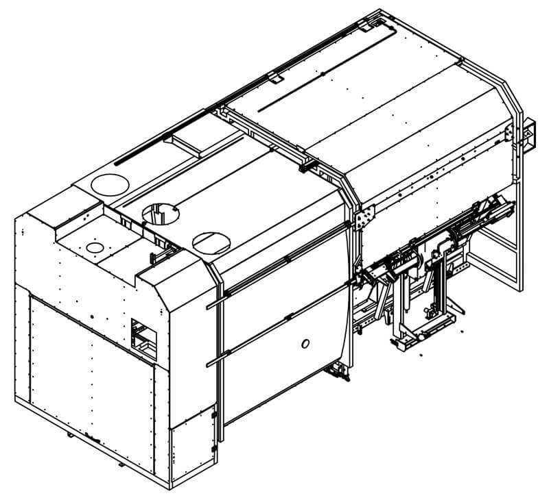
2. WASHING CHAMBER
STRUCTURE
The structure is made of aluminum alloy 6060 profiles, while the cladding is made of PE5754 aluminum-magnesium alloy, typically in sheet form, which offers good toughness both at room temperature and at low temperatures.
SLIDING DOOR
Like the washing chamber, it is also made of aluminum. Thanks to its sliding movement, it allows the door to be closed even in confined spaces. It is equipped with flat-jet nozzles for the external washing of the container.
DIRTY WATER COLLECTION AREA
At the bottom of the washing chamber there is an area designed to collect dirty water and solid residues that may be present inside the bin. To prevent solid particles from entering the pipes system, a stainless steel mesh filter is installed.
LOWER DOOR
To enable faster discharge of waste contained in the washing chamber, a large, fully sealed lower door is installed. The opening and closing of this door are operated by screws with knobs.
DIRTY WATER PUMP
Hydraulically driven, it transfers dirty water from the collection area to the central tank.
3. LIFTER
The device for lifting and tipping bins is mounted on the front right side of the equipment (in the direction of travel) and is suitable for handling bins compliant with DIN standards, with capacities of 1800, 2400, and 3200 liters. An optional device can also handle 800 and 1100-liter containers, with both flat and round lids.
The structure of the device is made of painted carbon steel. It is equipped with hydraulic cylinders for engaging the containers, while rotation is performed by a hydraulic actuator that ensures smooth and continuous movement.
The control system is located on the in-cab console, where the operator, through cameras, can safely handle and monitor all operations. Each phase is followed by cameras that sequentially display the previously described steps on the screen.
All lifting and washing cycles are controlled by sensors and encoders. The absence of even a single signal during the cycle will stop the equipment to prevent damage.
4. PTO GROUP
The washing cycle is activated via the vehicle’s gearbox power take-off, using the corresponding button on the control panel located in the cab.
5. HUDRAULIC SYSTEM
The hydraulic system of the bin-washing equipment, which operates the various functions and devices of the unit, is divided into two separate circuits:
- No. 1 for washing devices and the transfer pump
- No. 1 for the bin lifting/tipping device and all related operations
Each circuit, when in the standby phase, is unloaded through a solenoid valve dedicated to returning the oil to the tank. In addition, each circuit is protected by a properly calibrated pressure relief valve. Both circuits are powered by hydraulic pumps directly connected to the power take-off.
6. WATER SYSTEM
The water system is designed to draw clean water from the dedicated tank, pressurize it, and direct it to the final points of use.
Its main components are:
- High-pressure pump for internal and external washing, with special pistons, flow rate 60 L/min, maximum pressure 150 bar;
- Pneumatically operated valves for directing pressurized water to the various services;
- Rotating washing heads and nozzles;
- Water filter;
- Pressure relief valve.
The drive is provided by a hydraulic motor, which is in turn driven by a pump connected to the equipment’s power take-off.
7. WASHING SYSTEM
7.1 INTERNAL WASHING SYSTEM
The internal washing of the bins is carried out by two self-rotating heads mounted on a robot operated by hydraulic cylinders. During the washing cycle, the heads move vertically along the bin walls and maintain their position at height. The washing times can be set between 5 and 30 seconds and are repeatable.
7.2 EXTERNAL WASHING SYSTEM
The washing of the container’s external walls occurs sequentially after the internal washing and is performed by bars equipped with special flat-jet nozzles, mounted on the inner walls of the washing chamber and on the sliding door. The positioning of the bars, as well as the total number of nozzles, is designed according to the range of bins to be washed. The water pressure and type of jet ensure adequate cleaning of the bin’s external surface, with particular attention to the areas most exposed to dirt. An icon on the touch monitor allows the selection of the washing type: internal (default setting), internal and external, or lid washing.
8. ELECTRICAL SYSTEM
The electrical system oversees the operation of all solenoid valves and safety devices. All parameters can be set via the touch screen monitor located in the cab, which is connected to a PLC placed in a panel positioned at the rear of the equipment.
The system is equipped with protective fuses and includes a white work light for illuminating the operational area during nighttime and orange rotating beacons (one at the front and one at the rear of the vehicle) to signal the equipment’s operational phase. The equipment is also fitted with all lighting and signaling devices required by the current Highway Code, positioned to ensure maximum visibility during the machine’s operational phases, both while in transit and during bin-washing operations.
9. PNEUMATIC SYSTEM
The pneumatic system of the equipment supplies all devices, including safety components, which require operation using high-pressure air, normally regulated at 6 bar.
The air supply is drawn from the auxiliary user ports available on the vehicle, following the instructions provided by each manufacturer in their outfitter manuals.
The circuit also includes a pressure regulator with integrated pressure switches to monitor the actual pressure within the system, ensuring the proper operation of the machine.
10. CONTROL PANEL
The control buttons and monitoring devices for the equipment are located both on the touch screen monitor and on the armrest, positioned ergonomically within the vehicle cab.
Additionally, the monitor provides access to all controls for the various sensors and includes a section for modifying the equipment’s general parameters.
11. OUTFITTING
The equipment is completed with splash guards on the rear mudguards, and a user and maintenance manual.
The bin-washing equipment is manufactured in compliance with the Machinery Directive and is supplied with a CE Declaration of Conformity.
